


Static Electricity in Hazardous Locations: Your Complete Guide to Prevention and Protection
Static electricity poses a significant ignition risk in hazardous process industries, capable of causing catastrophic incidents when flammable materials are present. Understanding and controlling static electricity is essential for maintaining OSHA compliance and protecting workers in industrial environments.
Understanding Static Electricity as an Ignition Source
Static electricity is essentially electricity stuck in one place – unlike normal electrical circuits where charges flow continuously through a closed loop, static charges accumulate on isolated equipment ranging from tanker trucks to flexible intermediate bulk containers (FIBCs). When these accumulated charges discharge as sparks, they can ignite flammable atmospheres with devastating consequences.
The ignition risk occurs when electrostatically charged materials or equipment reach critical voltage levels. When the voltage exceeds the breakdown voltage of the gap between charged and grounded objects, rapid ionization creates a conductive path for charges to discharge as a spark. The total energy available for discharge depends on both the voltage (V) and capacitance (C) of the charged object.
Download the full Technical Paper – Newson Gale
Static electricity and its role as a potential ignition source in hazardous areas
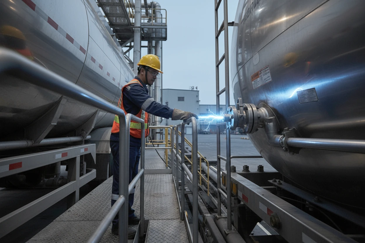
Learn why truck and railcar grounding is necessary.
A stationary electric charge, typically produced by friction, can cause sparks when those static electrons move from one object to another.
Regulatory Requirements and Compliance Standards
America’s Federal Regulations
The Code of Federal Regulations 29 CFR Part 1910 “Occupational Safety and Health Standards” mandates that all ignition sources in flammable atmospheres, including static electricity, must be mitigated or controlled. This establishes the legal framework requiring industrial facilities to implement comprehensive static control measures.
Canadian Requirements
Section 10.12 of Canada’s Occupational Health and Safety Regulations (SOR/86-304) specifically requires employers to implement standards from NFPA 77 “Recommended Practice on Static Electricity” when flammable substances and static electricity hazards are present.
European Standards
The ATEX Directive 2014/34/EU, Annex II, Section 1.3.2 states that “electrostatic charges capable of resulting in dangerous discharges must be prevented by means of appropriate measures”.
Industry Best Practices and Standards
Key Industry Standards for Static Control
| Standard | Publisher | Title | Metal Grounding Circuits | FIBC Type C |
|---|---|---|---|---|
| IEC TS 60079-32-1 | International Electrotechnical Commission | IEC TS 60079-32-1: Explosive Atmospheres, Electrostatic Hazards – Guidance | 10 Ω | 1 x 10⁸ Ω |
| NFPA 77 | National Fire Protection Association | NFPA 77: Recommended Practice on Static Electricity | 10 Ω | 1 x 10⁸ Ω |
| API RP 2003 | American Petroleum Institute | API RP 2003: Protection against Ignitions Arising out of Static, Lightning and Stray Currents | 10 Ω* | N/A |
| API 2219 | American Petroleum Institute | API 2219: Safe Operation of Vacuum Trucks in Petroleum Service | 10 Ω | N/A |
| IEC 61340-4-4 | International Electrotechnical Commission | IEC 61340-4-4: Electrostatic classification of Flexible Intermediate Bulk Containers | N/A | 1 x 10⁸ Ω |
*API RP 2003 states that 10 Ω is ‘satisfactory
These standards, produced by committees of technical experts, provide comprehensive guidance for identifying and controlling electrostatic ignition sources in hazardous locations.
Understanding Minimum Ignition Energy (MIE)
The Minimum Ignition Energy represents the lowest energy required to ignite specific materials. Understanding these values is critical for assessing static electricity risks in your facility.
Flammable Liquids & Gases
| Material | MIE |
|---|---|
| Methanol | 0.14 mJ |
| Benzene | 0.20 mJ |
| Toluene | 0.24 mJ |
| Ethyl Acetate | 0.46 mJ |
| MEK | 0.53 mJ |
| Acetone | 1.15 mJ |
Combustible Powders
| Material | MIE |
|---|---|
| Magnesium Stearate | 3 mJ |
| Polyethylene | 10 mJ |
| Cellulose Acetate | 15 mJ |
| Sulfur | 15 mJ |
| Aluminum | 50 mJ |
| Polypropylene | 50 mJ |
These values demonstrate that relatively small static discharges can ignite many common industrial materials.
Figures listed are illustrative examples of the MIE. Confirmation of the actual product MIE should be sought from the product supplier.
Real-World Scenarios – Equipment at Risk and Isolation Causes
Typical Equipment Capacitance Values
| Equipment | Capacitance (pF) |
|---|---|
| Tank Car | 1000 |
| Automobile | 500 |
| Person | 100-300 |
| Oil/Solvent Drum | 10-100 |
| Metal Scoop | 10-20 |
Understanding these isolation mechanisms is essential for implementing effective grounding strategies.
Common Causes of Electrical Isolation
| Equipment | Isolation Causes |
|---|---|
| Portable Drums | Protective coatings, product deposits, rust |
| Road Tankers | Rubber tires |
| Piping | Rubber/plastic seals, anti-vibration pads, gaskets |
| Rail Tankers | Grease, vibration pads isolating tank from rails |
| Hoses | Broken internal helixes and bonding connectors |
| FIBCs | Non-conductive fabric, damaged static dissipative threads |
Equipment at risk of static charge accumulation and what can cause electrical isolation.
Essential Operator Training Requirements
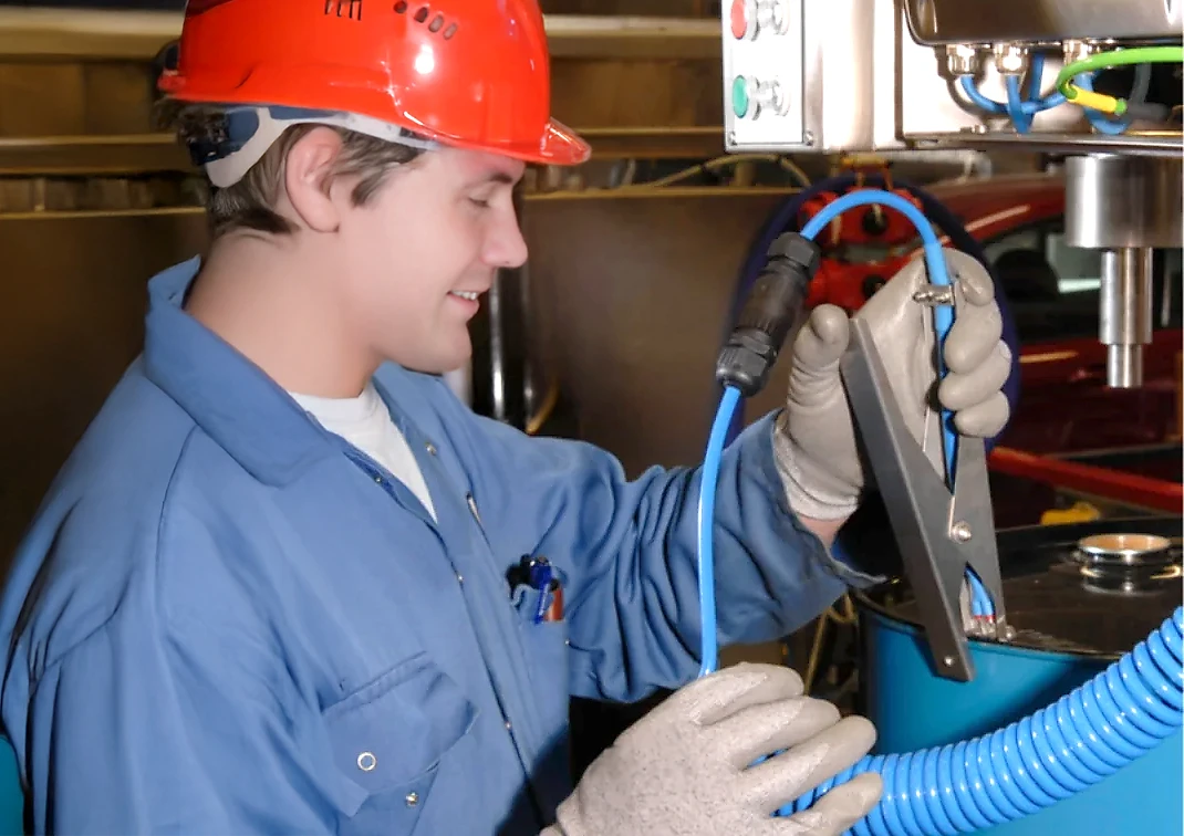
Comprehensive operator training cannot be neglected or treated as secondary, especially when bulk loading chemical products. Personnel operating in hazardous areas must receive thorough education about static electricity’s role as an ignition hazard, since they interact daily with the grounding and bonding systems that facilities have invested in and deployed .
Training must cover how grounding equipment functions properly, its correct application, and how these procedures integrate into the facility’s standard operating protocols. For typical applications such as drum grounding, workers must understand and practice establishing ground connections before operating and maintaining those connections until all activities are finished.
Workers need education about critical safety situations, including what happens when interlocked grounding systems lose connection mid-process, triggering automatic shutdowns like pump deactivation. Even after the equipment stops, material can continue moving through systems, maintaining the potential for dangerous static accumulation.
When workers observe damaged or modified equipment, including deteriorating cable insulation, they must know to immediately inform appropriate personnel—whether supervisors, safety coordinators, or maintenance teams—and refrain from operating the equipment until qualified personnel verify its safety and suitability.
Establishing Effective Static Grounding and Bonding Requirements
Creating Reliable Static Grounding and Bonding Systems
Protecting metallic equipment from static electricity buildup, especially during bulk loading and unloading operations, requires a systematic approach combining verified earth connections, precise resistance standards, and appropriate monitoring technology. Facilities must establish grounding systems that maintain less than 10 ohms resistance—the industry benchmark that ensures proper dissipation while detecting potential connection issues like corrosion or loosening.
Modern grounding solutions range from basic clamp connections to advanced monitoring systems with visual indicators and process interlocks, all designed to enforce the critical “Clamp On First, Clamp Off Last” protocol. While these systems verify equipment-to-ground connections, facility owners remain responsible for maintaining proper earth ground networks according to national standards. Success depends on correct installation, adherence to operating procedures, and never compromising safety by removing grounds during active processes.
Basic Grounding Requirements
When metallic equipment needs static protection, connect it to a verified true earth ground.
Earth Ground Specifications:
- Must have low resistance connection to earth’s mass
- Existing electrical and lightning protection grounds are adequate (NFPA 77, 7.3.1.6.1)
- Site owner’s responsibility to verify proper earth connection
Critical Resistance Standards
The 10-Ohm Benchmark:
- Resistance between equipment and earth ground must be <10 ohms
- Higher resistance indicates:
- Loose connections
- Corrosion problems
- Maintenance needed
- Standards: NFPA 77, 7.3.1.6.1 and IEC TS 60079-32-1
Grounding Equipment Options
Basic Systems:
- Simple clamp connections
- Manual verification required
Advanced Monitoring Systems:
- Visual status indicators showing 10-ohm connection
- LED displays change from:
- Red = Non-permissive (no ground)
- Flashing Green = Permissive (proper ground established)
- Continuous resistance monitoring
Interlock Systems:
- Prevents process startup without proper grounding
- Sends permissive signals to process controls
- Enforces “Clamp On First, Clamp Off Last” protocol
- Makes grounding the mandatory first step.
Important System Limitations
What Monitoring Systems DO:
- Verify connection between equipment and facility ground network
- Monitor resistance at 10 ohms or less
- Provide visual/interlock confirmation
What They DON’T Do:
- Verify facility’s ground network connection to earth
- Replace site owner’s responsibility for ground network maintenance
Installation Requirements
Critical Installation Guidelines:
- Follow manufacturer’s instruction manual exactly
- Maintain HAZLOC certification compliance
- Improper installation results in:
- Compromised safety
- Voided warranty
- Non-compliant operation
Operating Procedures
“Clamp On First, Clamp Off Last” Protocol:
NEVER:
- Remove ground connections during active processes
- Start operations before grounding is established
- Bypass grounding interlocks
ALWAYS:
- Establish grounding before any operation begins
- Maintain connection throughout entire process
- Remove grounding only after complete shutdown
Failure to follow these procedures risks static discharge incidents
SafeRack’s Comprehensive Static Control Solutions
Grounding and Monitoring Systems
SafeRack provides advanced grounding and monitoring systems designed to meet or exceed industry standards for static electricity control. Our grounding solutions include ground verification monitors that ensure proper connections before operations begin, maintaining the critical 10 ohm or less resistance requirement specified by NFPA 77 and IEC standards.
Our grounding systems feature visual indicators that switch from non-permissive (red) to permissive (flashing green) states when proper grounding is established. These systems can be interlocked with process controls to prevent material transfer until safe grounding is confirmed, supporting the essential “Clamp On First, Clamp Off Last” principle.
Understanding and Mitigating Static Electricity in Industrial Settings
On-Site Safety Assessments
SafeRack’s Regional Area Managers (RAMs) conduct comprehensive on-site evaluations to identify static electricity hazards specific to your facility. During these assessments, our experts engage with your safety, maintenance, and operations teams to understand workflow requirements and develop customized static control strategies.
These evaluations include analysis of existing grounding systems, identification of isolation points, and recommendations for equipment upgrades or procedural changes to ensure full compliance with applicable standards.
Integrated Safety Systems
Beyond grounding equipment, SafeRack offers complete loading terminal solutions incorporating multiple layers of static protection. Our systems include properly grounded loading platforms, gangways with integrated bonding, safety cages that prevent falls while maintaining electrical continuity, and spill containment systems that protect against static-generating liquid spills.
Effective static control requires comprehensive operator training. Workers must understand static electricity fundamentals, including how charges accumulate, discharge mechanisms, and the critical role of proper grounding procedures. Training should emphasize the correct use of grounding equipment within standard operating procedures and the importance of following the “Clamp On First, Clamp Off Last” principle.
Operators should be trained to recognize equipment damage such as fraying cables or corroded connections and understand the importance of reporting these issues immediately. They must also understand that removing grounding connections during material transfer can create dangerous static discharge conditions, even after equipment shutdown.
Source: Adapted from “Static electricity and its role as a potential ignition source in hazardous locations” by Newson Gale, a SafeRack supplier specializing in static grounding and bonding equipment for hazardous area operations.